Amie
An autonomous mobile platform for industrial floors — one unit that moves material and inspects the plant it moves through.
In development since February 2026 — target 2028

Concept render — design intent, not a photograph of hardware
The problem
Most plants run two fleets: one that moves things, and one that inspects things. Both traverse the same floor, on overlapping routes, at different hours.
Amie is our attempt to collapse that into one. A platform capable of carrying a load is already travelling past every asset on the route — the marginal cost of also listening to those assets is a sensor payload and the software to interpret it. The engineering problem is doing both without compromising either.
24/7
target continuous operation
± 2 cm
target localisation accuracy
4
sensing modalities fused
8 h
target runtime between charges
Autonomous dock approach and contact recharge — no operator intervention
3
independent supervision layers
0
cloud dependencies in the control path
Design targets for the current programme — not measured production figures
Architecture
Twelve subsystems,\n four layers
Perception
Tightly-coupled LiDAR-inertial odometry
Spinning LiDAR and an industrial IMU fused in a single factor graph rather than filtered in sequence. Pose stays observable through the featureless stretches — long blank aisles, roller doors — where scan-matching alone drifts.
Multi-spectral sensing
Stereo vision for semantics and texture, thermal for radiative signatures, and a contact microphone array for structure-borne sound. Each modality fails under different conditions; dust defeats vision long before it defeats LiDAR, and steam defeats both before it defeats acoustics.
Learned occupancy representation
Rather than a fixed voxel grid, the map is a learned implicit field queried at arbitrary resolution — dense where geometry is intricate, sparse across open floor. Memory scales with scene complexity instead of volume.
Autonomy
Vision-language-action task specification
Tasks are issued in natural language and grounded against the semantic map on-board — "collect from cell four, inspect the compressor on the way back" resolves to a route and a sensing plan without a bespoke integration per instruction.
Simulation-trained policies with domain randomisation
Navigation and docking policies trained across randomised friction, lighting, payload mass and sensor noise, then validated against physical hardware before release. The reality gap is treated as a discipline rather than a final tuning pass.
Energy-aware route planning
Routes are solved against remaining charge, queue priority and contested-corridor timing together, so opportunity charging is scheduled as part of the plan rather than triggered as an interrupt at a low-battery threshold.
Assurance
Deterministic control path
Motion control runs on a real-time kernel over a time-sensitive fieldbus, with the safety loop physically separate from the autonomy stack. A perception fault degrades behaviour; it cannot delay a stop command.
Runtime safety envelope
An independent monitor checks commanded motion against a formally specified envelope — speed against proximity, deceleration against payload inertia — and can veto the planner. The monitor is small enough to be reviewed line by line, which the planner is not.
Post-quantum telemetry
Fleet telemetry and over-the-air updates are signed and encrypted with post-quantum key exchange. Industrial assets stay in service for decades, so data harvested today outlives the cryptography protecting it.
Fleet
Decentralised coordination
Units negotiate routes, charging windows and task handoff between themselves against a shared map. There is no central dispatcher whose failure stops the floor.
Federated model improvement
Perception models improve from what the fleet encounters without raw sensor data leaving the site — gradients are aggregated, footage is not shipped. A defect one unit learns to recognise becomes recognisable to all of them.
Continuous digital twin
Every unit maintains a simulation counterpart fed by its own telemetry. Candidate policies are replayed against real recorded conditions before they are promoted to hardware.
Research lineage
Amie is where several of our practices converge. The reasoning behind each subsystem is published in full.
Formulations
What actually governs the behaviour
Four relations that decide how the platform estimates where it is, when it may move, what it hears in a bearing, and which route it takes.
Pose graph optimisation
PerceptionX* = arg minX Σij ‖ h(xi, xj) − zij ‖2Σij
The trajectory is not integrated forward from odometry; it is the configuration that best explains every constraint at once, each weighted by its own measurement covariance. This is why loop closure corrects the whole history rather than only the present pose.
x — poses · z — relative measurements · h — measurement model · Σ — measurement covariance
Safe velocity bound
Assurancevcmd ≤ −amaxtr + √( amax2tr2 + 2amaxdfree )
Commanded speed is capped so the platform can always halt inside the free space it can currently sense, accounting for reaction latency. The runtime monitor evaluates this independently of the planner and can veto a command the planner considers valid.
d_free — sensed clear distance · a_max — deceleration limit at current payload · t_r — worst-case reaction time
Bearing defect frequency
Condition monitoringBPFO = (n / 2) · fr · ( 1 − (d / D) cos φ )
A failing outer race excites a specific frequency set by the geometry of the bearing and its shaft speed. Knowing where to look turns anomaly detection into a narrowband question, which is what lets a passing platform diagnose an asset in seconds rather than requiring a dedicated survey.
n — rolling elements · f_r — shaft frequency · d — element diameter · D — pitch diameter · φ — contact angle
Energy-aware route cost
AutonomyJ = Σij ( wt tij + we Eij ) s.t. SoC(t) ≥ SoCmin ∀t
Routing solves time and energy together under a state-of-charge constraint, so opportunity charging is scheduled as part of the plan. Optimising time alone produces a fleet that is fast until it is simultaneously flat.
E — segment energy · SoC — state of charge · w — weighting between throughput and endurance
Reference model
The chassis, in three dimensions
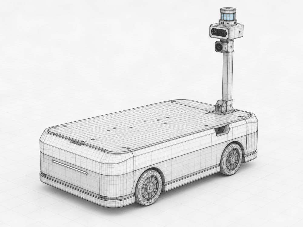
Exterior envelope
Deck, wheel housings and mast placement
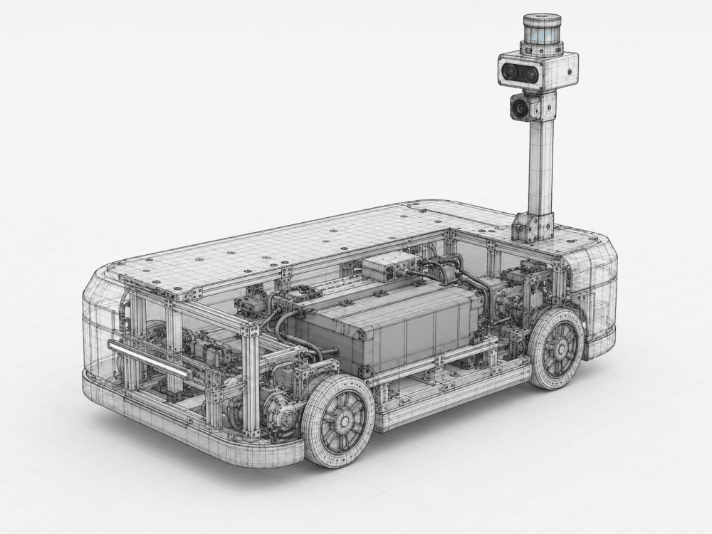
Internal structure
Frame, battery pack, drive units and harness routing
Reference geometry — sensor placement and envelope studies
Mast height set by stereo baseline and aisle clearance
Battery and drive units carried below the deck line
Programme status
Where it actually stands
Stated plainly, because a research programme that overstates its position is worth less than one that does not.
- Programme start
- February 2026
- Target completion
- 2028
Phase 01
Perception and mapping
Sensor fusion, learned occupancy representation, and the mapping pipeline validated against recorded plant environments.
Phase 02
Autonomy in simulation
Navigation, docking and inspection policies trained under domain randomisation and evaluated in the digital twin.
Phase 03
Hardware integration
Deterministic control path, independent safety monitor, and the physical sensor payload on a reference chassis.
Phase 04
Supervised pilot
A single unit on a real route under supervision, measured against the design targets rather than against a demo script.
Running a floor where this would be useful?
We are looking for pilot customers to shape the programme against real routes, real assets and real duty cycles — and to be first to run it.
Talk to the team